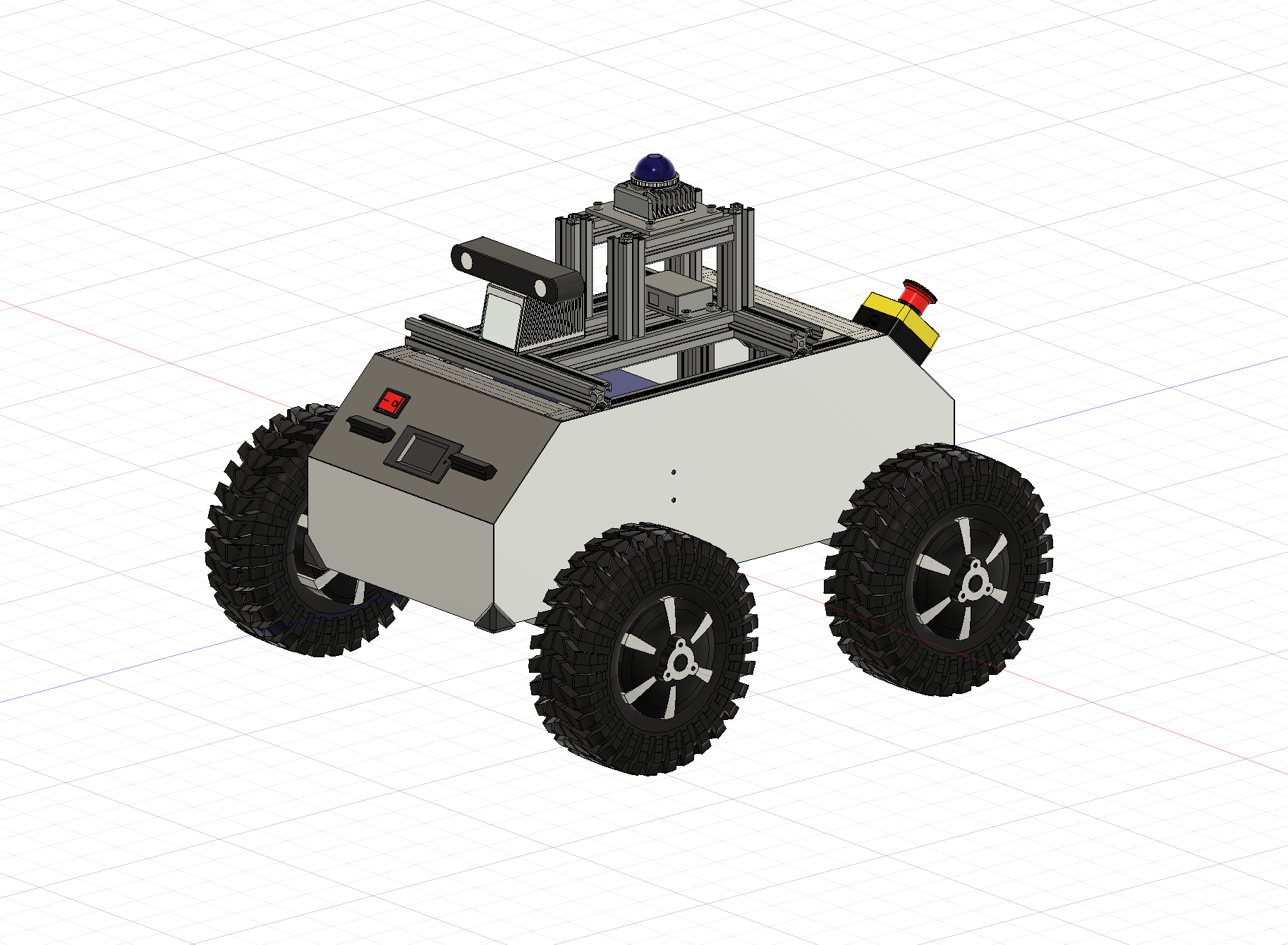
I wanted a robot that could handle rough outdoor terrain — grass, gravel, slopes — for autonomous navigation research. The obvious choice was something like a Clearpath Husky, but those cost $20k+. So I designed one myself in Fusion 360 and built it from aluminum extrusion and off-the-shelf parts.
잔디, 자갈, 경사면 같은 거친 야외 지형에서 자율주행 연구를 할 수 있는 로봇이 필요했습니다. Clearpath Husky 같은 상용 로봇이 적합했지만 가격이 2천만 원 이상이었습니다. 그래서 Fusion 360으로 직접 설계하고 알루미늄 프로파일과 시중 부품으로 조립했습니다.
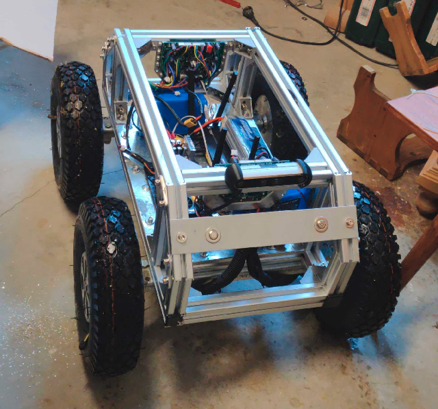
The first attempt used hoverboard motors — cheap, but they couldn't generate enough torque at low RPM for skid steering. The wheels would just stall on turns. Switching to geared BLDC hub motors with a 5:1 planetary gearbox solved that, but introduced a new problem: the hall sensor signals were too noisy for the ODrive controllers. Ended up soldering twelve capacitors across the hall lines to clean them up.
처음에는 호버보드 모터를 사용했습니다 — 저렴했지만 저속 회전 시 스키드 스티어링에 필요한 토크가 부족했습니다. 회전할 때 바퀴가 멈춰버렸습니다. 5:1 유성기어가 내장된 기어드 BLDC 허브 모터로 교체해 해결했지만, 홀 센서 신호가 ODrive 컨트롤러에 너무 노이즈가 많은 새로운 문제가 생겼습니다. 결국 홀 라인에 커패시터 12개를 납땜해서 신호를 정리했습니다.
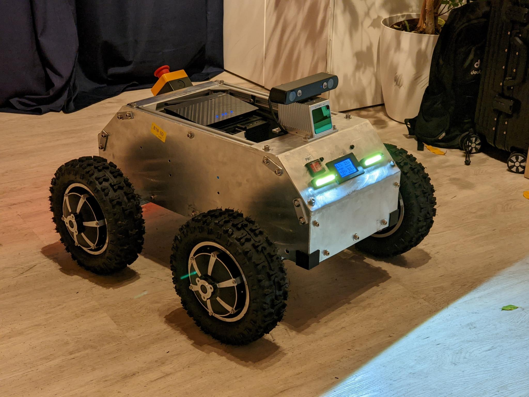
That's what building hardware is like — every solution creates the next problem. But the result is a robot that can carry a Velodyne lidar and a Jetson AGX through a field, and it cost a fraction of what a commercial platform would.
하드웨어를 만든다는 건 이런 겁니다 — 하나를 해결하면 다음 문제가 생깁니다. 하지만 결과적으로 Velodyne 라이다와 Jetson AGX를 싣고 들판을 달릴 수 있는 로봇이 완성되었고, 상용 플랫폼의 몇 분의 일 가격으로 만들었습니다.
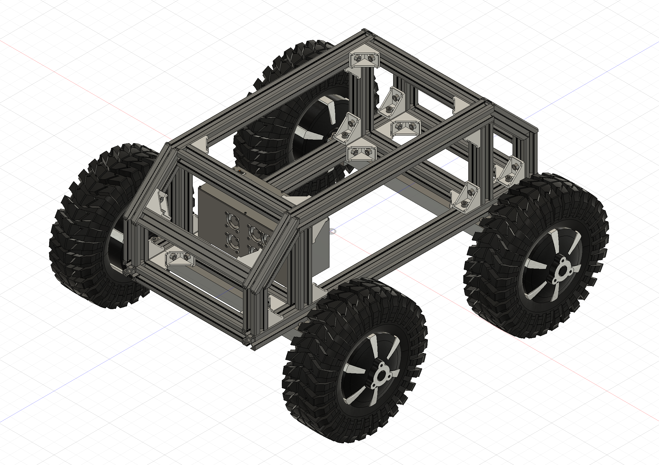
The chassis is built from 30cm aluminum extrusion segments — about 4–5 meters total — with 1mm aluminum sheet panels forming the body. Forty brackets with T-slot nuts hold it all together. The whole thing was designed in Fusion 360 and can be assembled with basic hand tools.
섀시는 30cm 알루미늄 프로파일을 총 4~5미터 정도 사용하여 제작했고, 1mm 알루미늄 판재로 외장을 구성했습니다. T-슬롯 너트가 달린 브래킷 40개로 전체를 조립합니다. Fusion 360으로 설계했으며 기본 공구만으로 조립할 수 있습니다.
The goal was something one or two people could lift, while still being tough enough for uneven terrain. No machined custom parts — just extrusion, sheet metal, 3D-printed brackets, and bolts.
한두 명이 들어올릴 수 있으면서도 비포장 지형을 버틸 수 있는 구조를 목표로 했습니다. 별도의 가공 부품 없이 프로파일, 판재, 3D 프린팅 브래킷, 볼트만으로 제작했습니다.
The first attempt used hoverboard motors, but they didn't have enough torque at low RPM for skid steering with ~25cm wheels. The fix was switching to in-hub geared BLDC motors (phub-11hs) — 48V, 500–800W, with a 5:1 planetary gearbox delivering 70 Nm per wheel.
처음에는 호버보드 모터를 사용했지만, 약 25cm 바퀴로 스키드 스티어링을 하기에는 저속 토크가 부족했습니다. 이를 해결하기 위해 인허브 기어드 BLDC 모터(phub-11hs)로 교체했습니다. 48V, 500~800W 사양에 5:1 유성 기어박스로 바퀴당 70 Nm의 토크를 냅니다.
Two ODrive 3.6 boards handle motor control with sinusoidal commutation. Hall effect sensors on each motor required 22µF capacitors for signal filtering — twelve total across the four motors.
ODrive 3.6 보드 2개로 사인파 정류 방식의 모터 제어를 합니다. 각 모터의 홀 센서 신호 필터링을 위해 22µF 커패시터가 필요했으며, 네 모터에 총 12개를 사용했습니다.
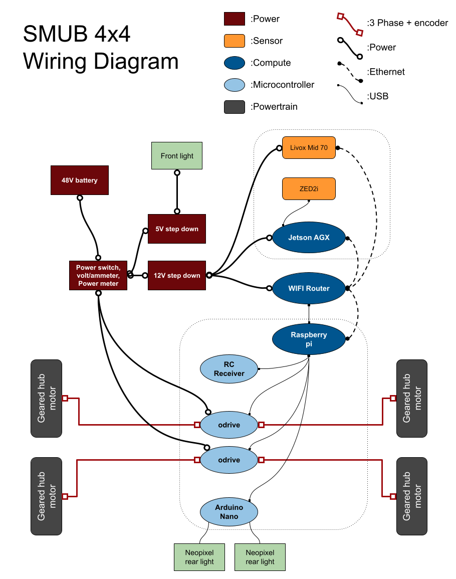
- Compute: Raspberry Pi (primary) + NVIDIA Jetson AGX (sensor processing)
- Motor control: 2× ODrive 3.6, 56V, sinusoidal commutation
- RC control: FlySky FSi6B via USB-to-TTL adapter
- Networking: Wireless router for inter-device comms
- Power: 48V battery, step-down converters (48V→12V, 48V→5V), XT60 connectors
- Safety: Emergency stop wired to ODrive nRST pin
- Display: Front panel LCD (V/A/W meter) + OLED for ROS messages
- Lights: Arduino Nano driving Neopixel LED ring — turn signals, reverse, brake
- 컴퓨팅: Raspberry Pi (메인) + NVIDIA Jetson AGX (센서 처리)
- 모터 제어: ODrive 3.6 2개, 56V, 사인파 정류
- RC 제어: FlySky FSi6B (USB-to-TTL 어댑터 연결)
- 네트워킹: 무선 라우터로 장치 간 통신
- 전원: 48V 배터리, 강압 컨버터 (48V→12V, 48V→5V), XT60 커넥터
- 안전장치: ODrive nRST 핀에 연결된 비상 정지 스위치
- 디스플레이: 전면 패널 LCD (V/A/W 미터) + ROS 메시지용 OLED
- 조명: Arduino Nano로 구동하는 Neopixel LED 링 — 방향지시등, 후진등, 제동등
The platform supports swappable sensor configurations depending on the task:
용도에 따라 센서 구성을 교체할 수 있습니다:
- Depth cameras: Intel RealSense D435 + T265 (odometry)
- Stereo: Stereolabs ZED2i
- 360° camera: Ricoh Theta V
- 2D lidar: RPLidar A1
- 3D lidar: Velodyne Puck, Livox Mid 70
- 뎁스 카메라: Intel RealSense D435 + T265 (오도메트리)
- 스테레오: Stereolabs ZED2i
- 360° 카메라: Ricoh Theta V
- 2D 라이다: RPLidar A1
- 3D 라이다: Velodyne Puck, Livox Mid 70
Everything runs on ROS. Custom nodes handle ODrive communication and encoder reading. The RC controller publishes cmd_vel commands, and the rear LEDs respond to velocity — mimicking real vehicle lighting behavior (indicators, reverse, braking).
전체 시스템은 ROS로 구동됩니다. 커스텀 노드가 ODrive 통신과 엔코더 읽기를 처리합니다. RC 컨트롤러가 cmd_vel 명령을 발행하면 후방 LED가 속도에 반응하여 실제 차량처럼 방향지시등, 후진등, 제동등 기능을 수행합니다.
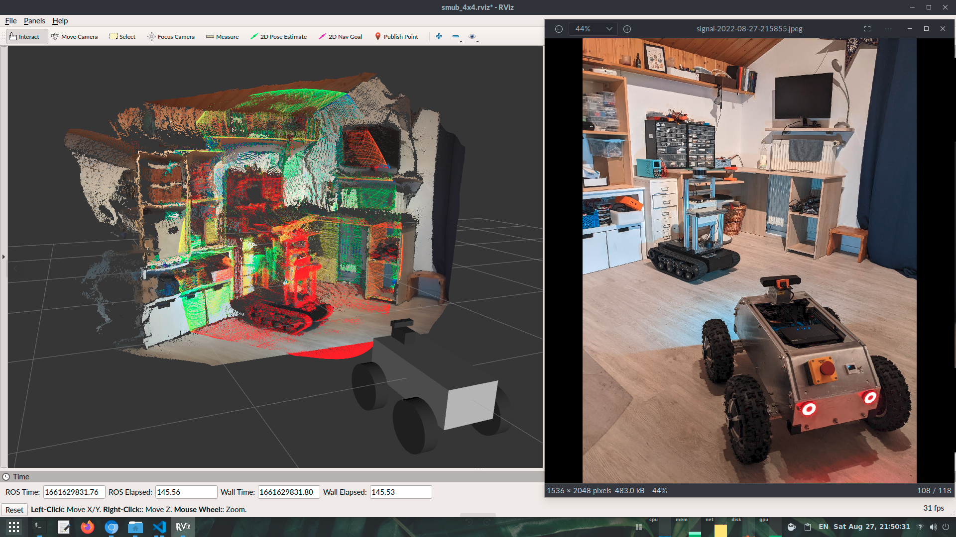
Sensor data feeds into RViz for visualization. The wireless router lets the Raspberry Pi and Jetson communicate over ROS topics, so sensor processing can be offloaded to the GPU.
센서 데이터는 RViz로 시각화됩니다. 무선 라우터를 통해 Raspberry Pi와 Jetson이 ROS 토픽으로 통신하므로, 센서 처리를 GPU로 분산할 수 있습니다.
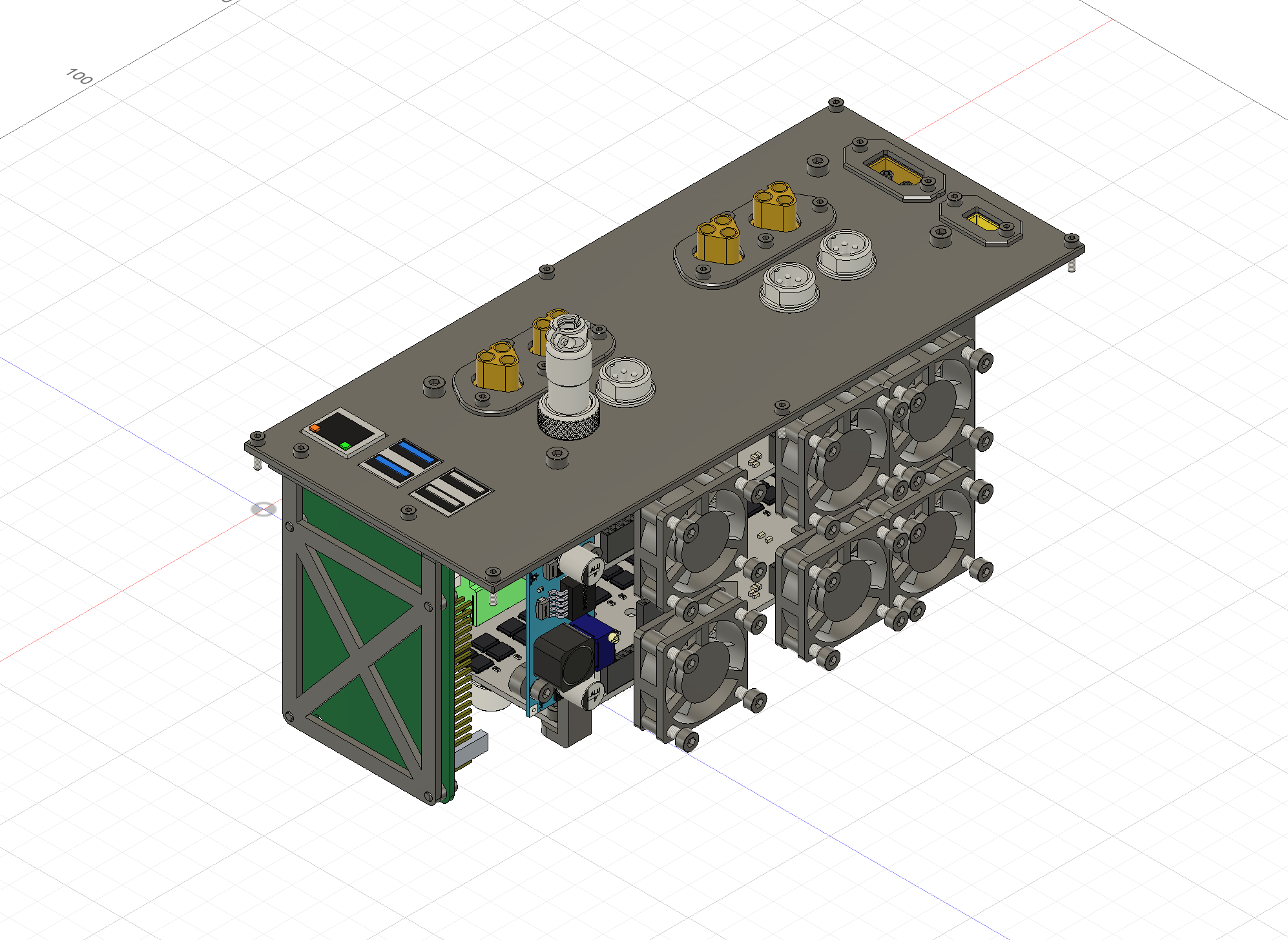
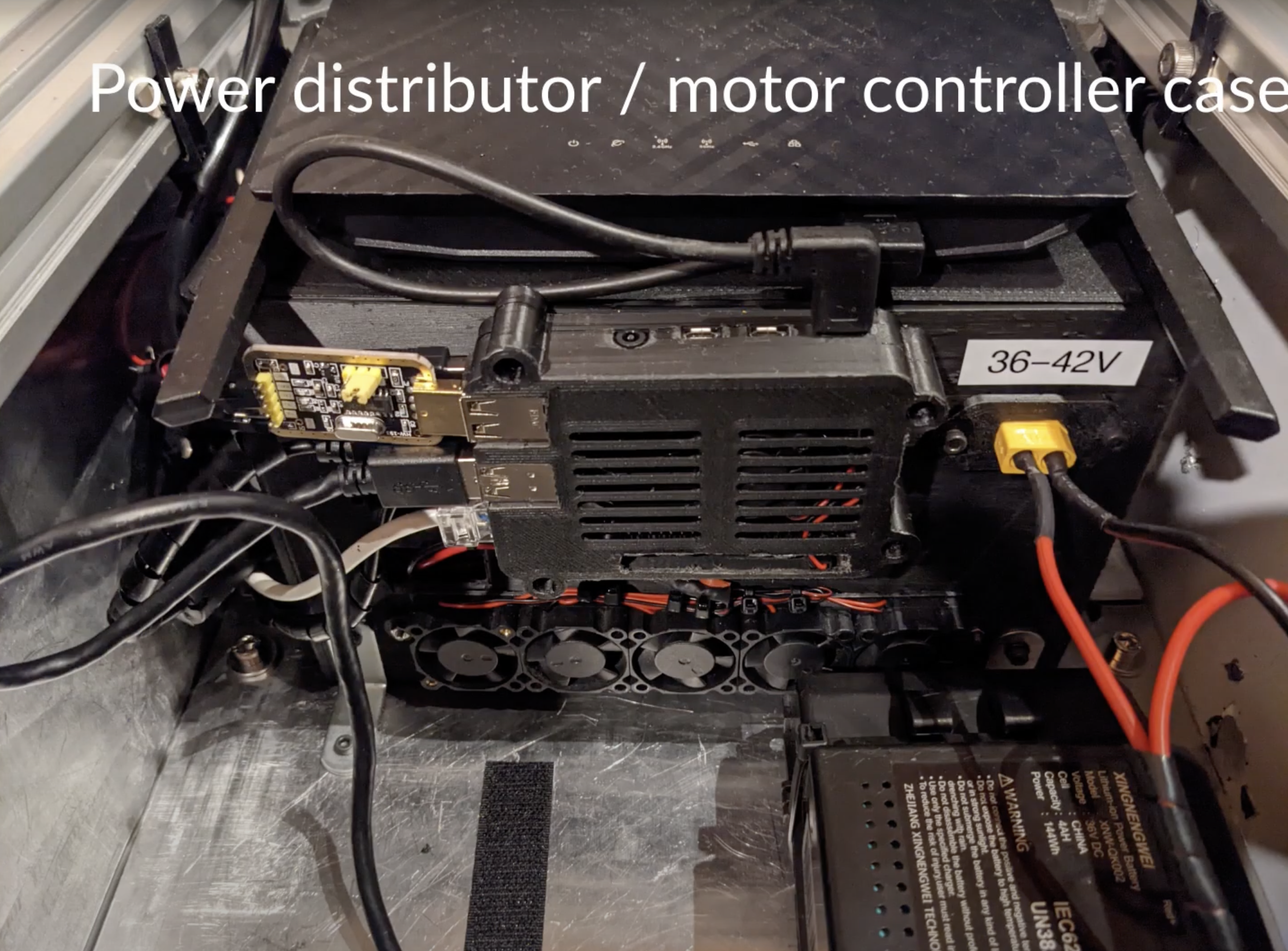
Redesigned controller box컨트롤러 박스 재설계
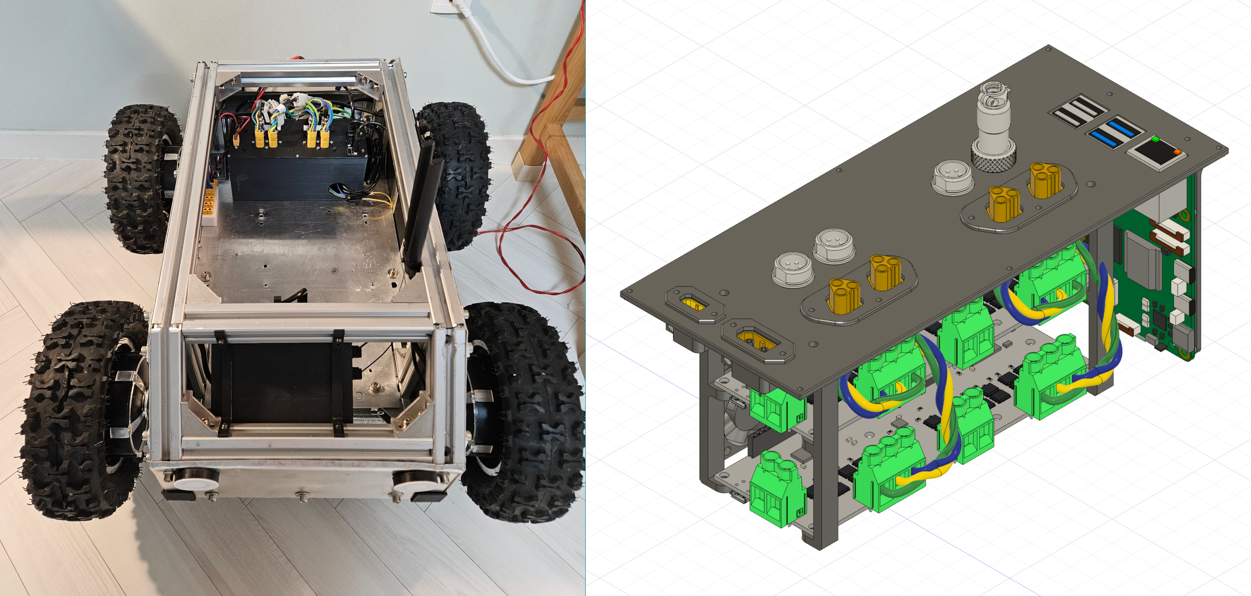
The original enclosure was a mess — the Raspberry Pi was mounted externally with double-sided tape, and the ODrives were crammed in with hastily-added fans. The new box fixes all of that with proper connectors and component integration.
기존 인클로저는 엉망이었습니다. Raspberry Pi는 양면테이프로 외부에 붙여놓았고, ODrive는 급하게 추가한 팬과 함께 억지로 넣어둔 상태였습니다. 새 박스는 적절한 커넥터와 부품 통합으로 이 모든 문제를 해결했습니다.
MT60 connectors for three-phase motor wiring. GX12 5-pin screw-in connectors for Hall encoders — because a loose encoder connection means an uncontrolled wheel spinout.
3상 모터 배선에는 MT60 커넥터를, 홀 엔코더에는 GX12 5핀 나사식 커넥터를 적용했습니다. 엔코더 연결이 느슨해지면 바퀴가 제어 불능으로 공회전하기 때문입니다.
- Jetson Xavier AGX — case design + PCI USB hub integration
- 1000 Hz IMU — MW-AHRS-X1 replacing ZED camera's 400 Hz for better lidar-inertial odometry
- Transformer-based visual navigation
- Multi-lidar SLAM — Livox Mid70 + Velodyne VLP-16
- Robotic arm — evaluating RoArm-M3 Pro for LeRobot integration
- Jetson Xavier AGX — 케이스 설계 + PCI USB 허브 통합
- 1000 Hz IMU — ZED 카메라의 400 Hz를 대체하는 MW-AHRS-X1로 라이다-관성 오도메트리 개선
- 트랜스포머 기반 비주얼 내비게이션
- 멀티 라이다 SLAM — Livox Mid70 + Velodyne VLP-16
- 로봇 팔 — LeRobot 통합을 위해 RoArm-M3 Pro 평가 중