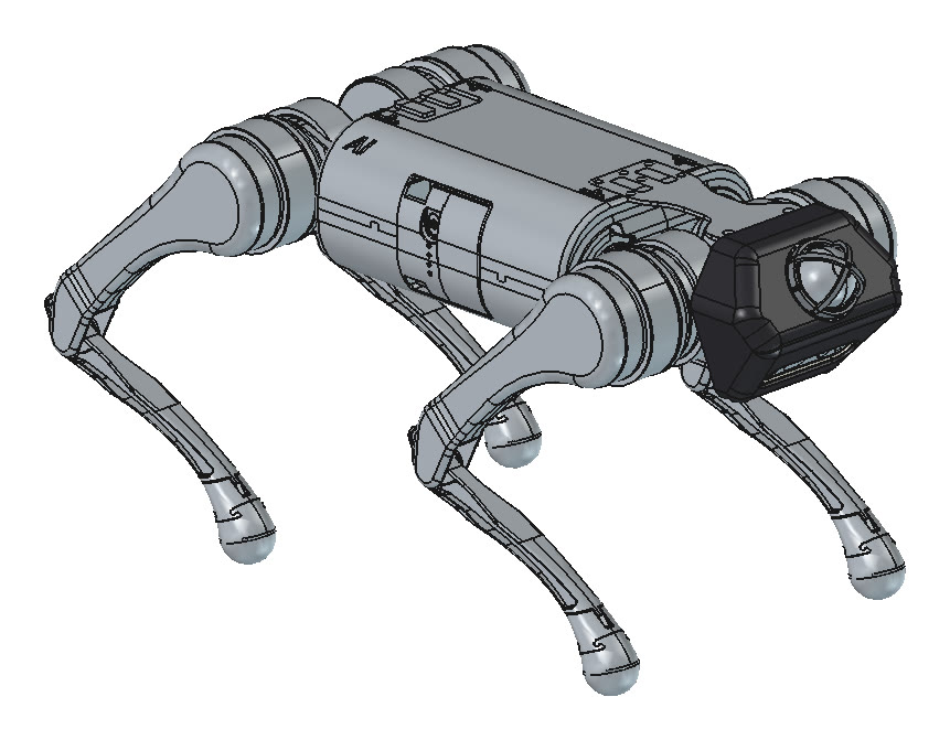
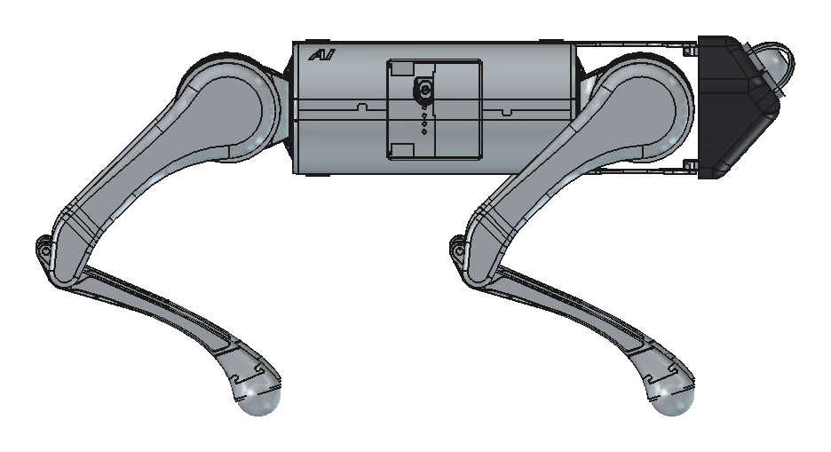
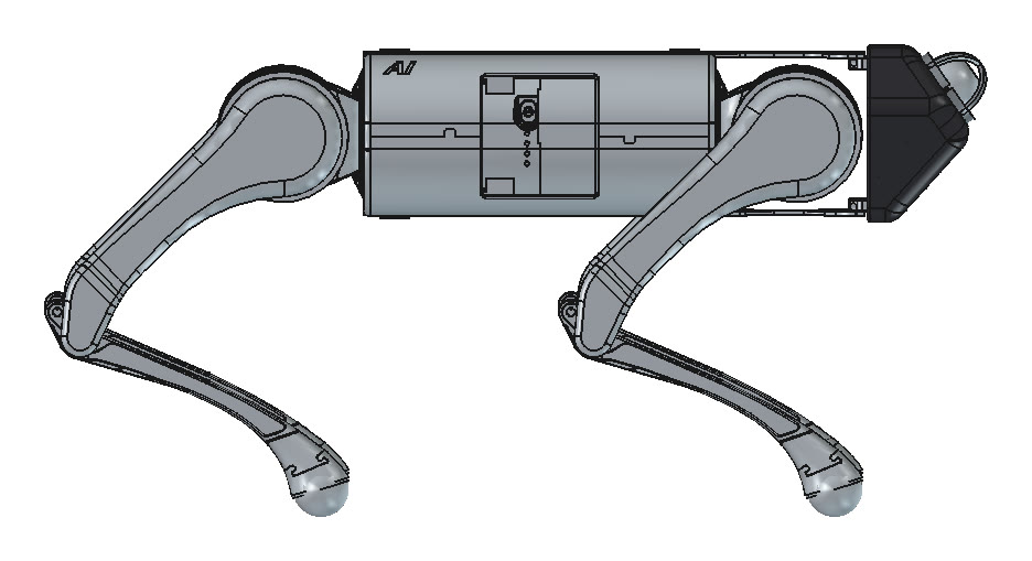
I took the A1's stock head off and designed a new one that carries a Livox Mid-360 lidar next to the RealSense D435. It has three printed parts: a rigid mount, a filler block and a TPU bumper. It bolts to the robot's existing eight-screw bracket pattern. I ran a linear impact study on it and went through three revisions to Rev C. Rev D3 then re-pitched both sensors, the lidar tilted up and the camera down, and Rev D3.1 reinforced it after its impact study. Rev D3.1 beat Rev B in 8 of 12 impact cases. Rev D3.3, the current design, drops the hood walls: the filler forms the whole head and a separate plate carries the lidar. Its impact study found a thin neck in the mount behind the lidar: a margin weak spot rather than a failure, with a fix designed but not yet analysed.
September 24 to October 7, 2026. Parametric FreeCAD script, CalculiX for the FEM.
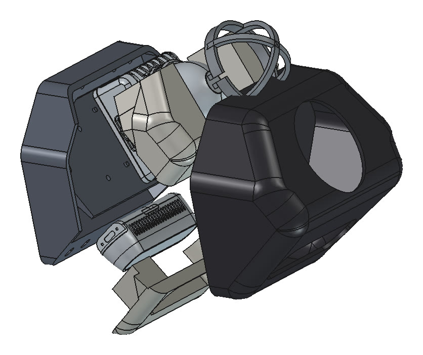
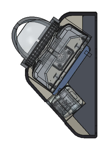
Rev D3.3 on the A1, rendered from the CAD: lidar on top, D435 below, the whole front formed by filler under a TPU skin. The arches over the dome are a bought slip-on guard.
Why a lidar on the nose
The D435 is a forward-facing depth camera. The Mid-360 scans a full circle around its own axis, and it has its own IMU. The locomotion papers also use both kinds of sensor. DreamWaQ++, one of the papers I'm reproducing, builds its terrain grid from a D435 on the Go1 and from Ouster or Livox lidars on other robots. This page covers only the mechanical side: giving both sensors a fixed, protected place on the body.
I also wanted to keep the layout I already had in the CAD. The D435 stands upright to the left of the lidar, and both point forward, tilted 10° down. The head is built around that layout.
The design
This section describes Rev C, the first complete design, with the sensors side by side. Rev D3 and D3.1 stacked them and are covered in the log and the impact study below; the script and the assembly approach carried over.
The whole head comes from one parametric FreeCAD script with every dimension as a named setting. Each run rebuilds all three parts and checks overlaps, assembly paths and wall thickness, so changes went into settings, not hand-edited geometry.
Three parts
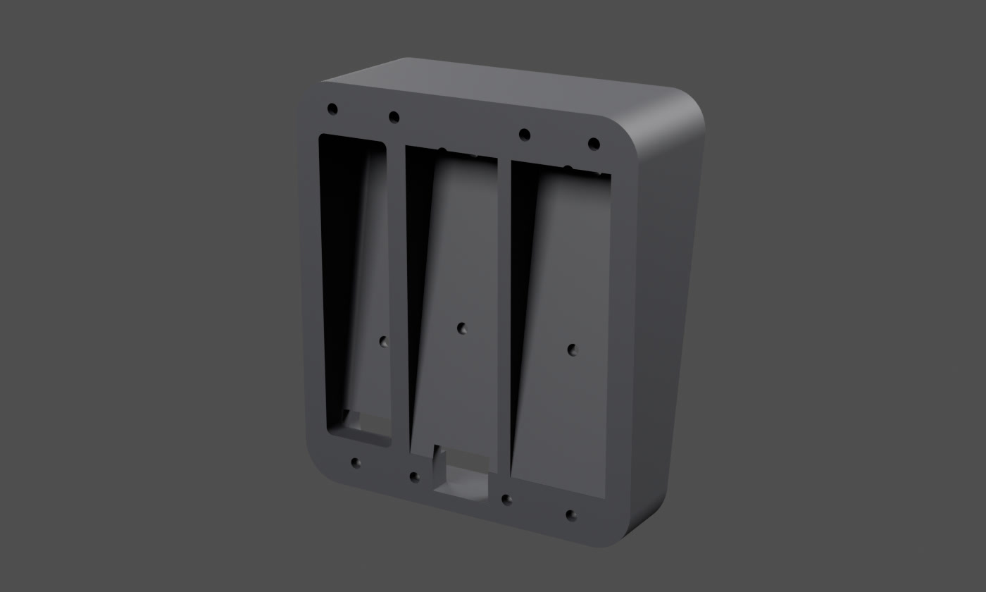
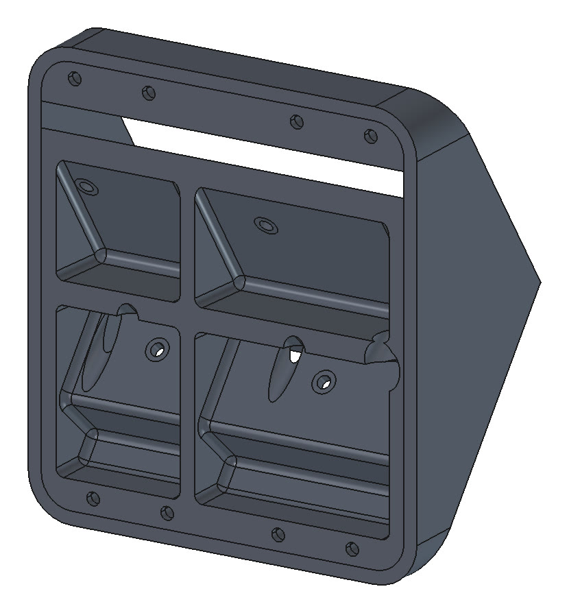
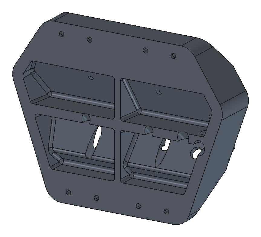
Mount. A rigid wedge plate with a hood around it, 105 × 117 mm outside. The sensors are tilted, so the gap between them and the body runs from about 2 mm at the bottom edge to about 13 mm at the top. The plate fills that gap, so it's thickest at the top, where the leverage is highest. From behind it's hollowed into three pockets, separated by ribs. Hood walls are 3.5 mm thick. About 152 g if printed solid.
Filler. A block that fills the hood around both sensors, so the soft front face has solid backing everywhere. It slides in along the sensors' 10° axis. A tunnel along its underside carries both right-angle plugs and their cables. Its front collar carries the rounded outer edges. About 38 g at 25% infill.
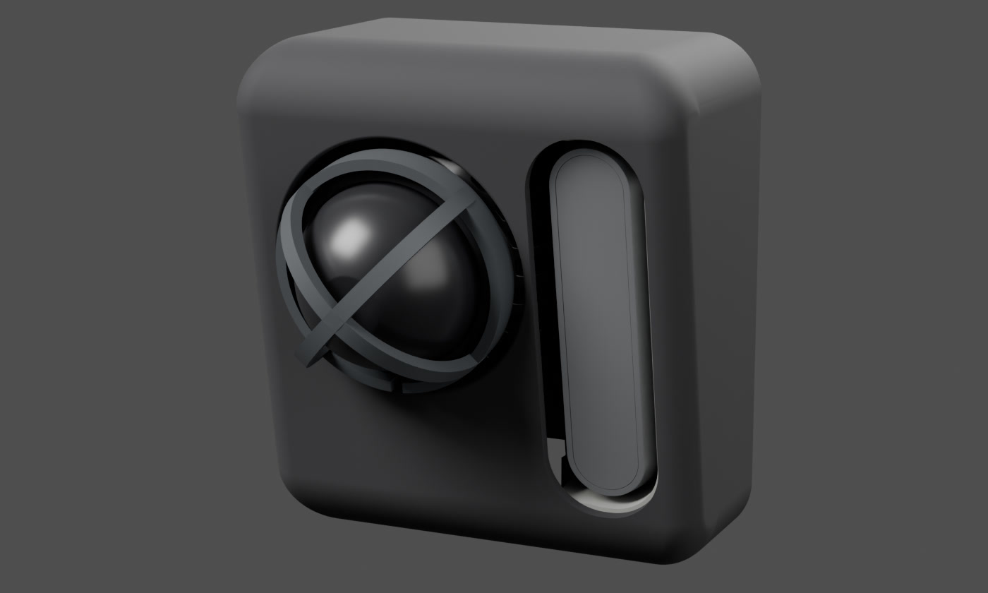
Bumper. A 2.5 mm TPU 95A skin over the hood, plus a front face. The face has a round Ø62 mm opening for the lidar and its dome guard, and a slot for the D435. A 2 mm lip snaps behind the hood all round. About 86 g.
I chose a rigid mount under the TPU because TPU on its own would just fold and let the ground hit the sensors. The rigid mount and the filler take the hit. The TPU spreads it out and softens the peak.
Rev C. From the front. The bumper hides the mount, the screws and the cables.Rev C. The mount from behind (the side that faces the body). Eight holes for heat-set inserts sit around the rim. The narrow pocket on the left is behind the D435 and the two on the right are behind the lidar. The cable slot is at the bottom centre.
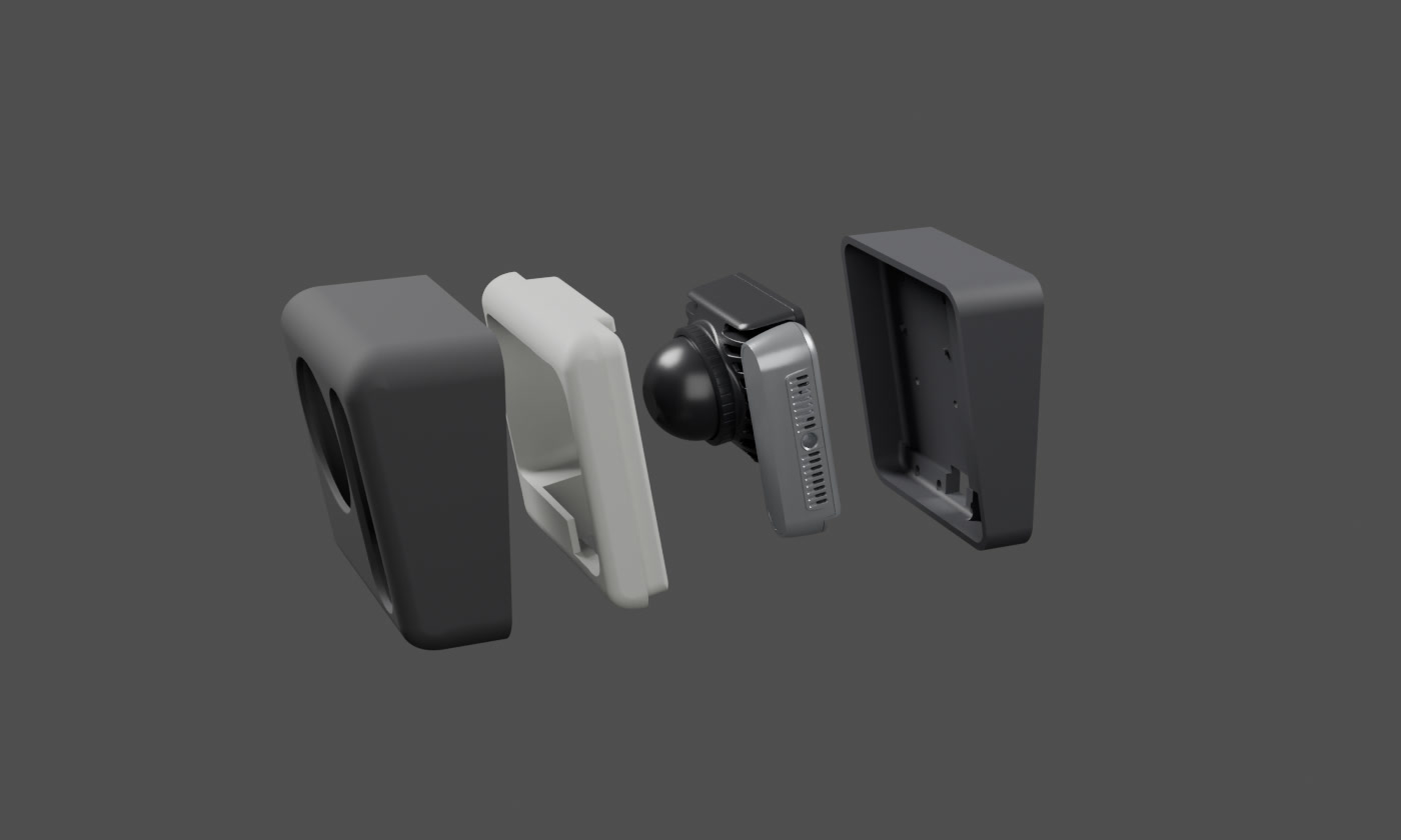
Rev C. Exploded, front on the left: bumper, filler, the two sensors, mount. The filler is shown light so it stands apart. The mount's material is discussed under Materials below.
Assembly order
Sensors onto the mountM3 screws from behind, through the open pockets. The Mid-360 also sits on two locating pins.
→
Plugs and cablesRight-angle M12 and USB-C plugs. The cables go down through the slot into the body's front cavity.
→
Filler, then bumperThe filler slides in along the sensor axis. The bumper slides on from the front and holds it in place.
→
Head onto the bodyEight M3×12 screws from inside the body, through the brackets, into heat-set inserts.
How it got there
A one-piece wedge plate
Both sensors have M3 holes on the face toward the body (four on the Mid-360, two 45 mm apart on the D435), so they screw straight onto a plate. The catch was assembly: once the sensors are on, they cover or nearly cover three of the four top body bolts. I settled on one plate and moved the sensors forward to make room for it: the lidar by 7 mm and the D435 by 13 mm.
Where the cables go
The lidar's straight connector sticks out 5–7 cm with its cable bend. Pointing it down would hang it below the belly, and the A1 rests on its belly when it lies down. I briefly flipped both sensors so the connectors pointed up. Then I remembered I have a right-angle M12 plug, and the lidar cable has almost no overmould. So the sensors went back to their original orientation, connectors down. Both plugs now drop into a slot between the bottom brackets.
Filler, round opening, a full lip
A round, larger lidar opening for the dome guard; the lidar raised to just under the top screws; a filler so "the thin flat part of the tpu doesn't just float there"; one continuous lip instead of two side tabs. Then I noticed that the hood's curled front lip would block the filler and the hex key to the top and bottom screws. The hood went back to straight walls, and the rounded edges moved onto the filler's collar. From then on the script checked on every run that the filler can slide in.
Three filler bugs
I asked about a slit along the bottom of the filler, which turned up three geometry bugs. The cable tunnel had a flat floor, so it broke through the rounded bottom edge. Trimming for slide-in in 2 mm steps had left a staircase. And the collar had been clipped 2.5 mm short all round. After fixing them I added a check for anything thinner than 1.2 mm. It caught a 1.3 mm wall between the two sensor cutouts, which are now merged into one opening.
Heat-set inserts, screws from inside
Taking the stock head off the robot showed that the screws come from inside the body, through U-shaped brackets, into the head, so the mount needed heat-set inserts. They go in from the front, so screw tension pulls each insert against a 2 mm solid web rather than out of its pocket. Otherwise "we risk the whole head just sliding off". The brackets were damaged when I took the head off, so I redrew them for reprinting: the countersunk recess is now flush, and the part is 1 mm thicker.
Impact study, Rev A to Rev C
I asked for a material analysis under different impacts. The first run found that the hood walls were the weak spot. Rev B thickened them from 2.5 to 3.5 mm and added fillets at the step between the sensor pads. A second study with the filler bonded in followed, and then Rev C. The details are below.
Rev D3: lidar up, camera down
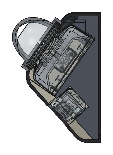
The Mid-360 has a 38° blind cone around its spin axis, so on Rev B and C it saw no ground straight ahead past about 0.3 m. Rev D3 stacks the sensors: the lidar on top, pitched 35° up so the blind cone clears the ground ahead and it covers about 0.2–5 m in front, and the D435 below, pointing 40° down for dense near terrain at 0.1–1.5 m. In side view the lower face is one slope from just under the lidar to the bottom of the back plate, with the D435 flush in it. The footprint, bumper size and eight-insert bolt pattern are the same as Rev C. Its impact study is below.
Rev D3.1: reinforced and centred
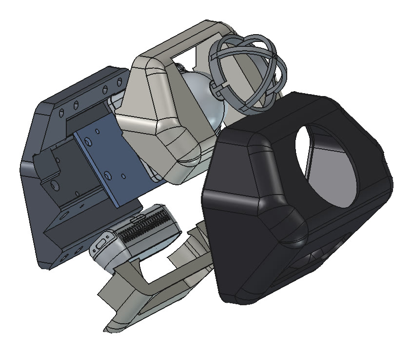
The D3 study found two weak zones, so D3.1 reworks the mount: a 12 mm top flange that closes D3's 7 mm slot, and solid plate around the inserts and across the top band. The side walls are trimmed so the filler and TPU form the nose. Both sensors are now centred on the robot; D3 had pushed the lidar 16 mm left to fit its plug. The front is a hexagon, 156 × 122 mm over the TPU. The lidar is still 35° up; the D435 now points 42° down. With sensors the head weighs about 0.75–0.82 kg, depending on the filler material, against about 0.58 kg for Rev B.
From the side: the wedge front, with the lidar tilted up so its blind cone clears the ground ahead.
Rev D3.3: no hood walls, a plate for the lidar
D3.3 drops the mount's hood walls. The filler now forms the whole head in front of the mount and is held on by the TPU bumper, with no screws. The lidar gets its own 6 mm plate: four countersunk M3 screws hold the Mid-360 to it, and four more fix it to the mount into hex-nut sockets in the back of the pad. The D435 is fixed with two countersunk M3 screws from the back of the mount. The mount itself is rebuilt from filleted side profiles, and the bumper's back lip is cut to 1.5 mm. The sensor poses are the same as D3.1.
Rev D3.3 from the side.
The impact study
CalculiX only does linear statics, so each case is a static reference load: 1 kN for impacts, 100 g for the sensors' own inertia. The rigid mount is held only at its eight insert webs. One solve per case covers every material, since linear stress scales with load. To turn force into impact energy, the TPU (or the dome guard, for a hit through the lidar) acts as a spring in series with the structure: the energy absorbed before the first point yields is F²/2k. I used two reference energies. A trip into an obstacle at walking pace is estimated at 3.5 J, and a nose-down tip-over from standing at 8.6 J. The trip assumes about half of the 14 kg robot, 7 kg, hitting at 1 m/s.
There are twelve load cases. Three are 100 g in each direction. Then a head-on hit through the dome guard and lidar, a face-plant on the rim, top and side impacts, a 45° top-front edge, and all four corners. Five materials: MJF PA11 and PA12, and FDM PA-CF, PETG and PLA. For FDM I used the strength across the layers, since the hood walls print upright and bend across them.
Rev A: the walls were the weak spot
The sensor g-loads were never a problem. At 100 g the worst stress was 13.4 MPa, next to a lidar screw hole. That's a safety factor of 3.6 in PA12 and 2.1 even in PLA. The screws and inserts weren't the limit either: each 2 mm web takes roughly 900 N before shearing, against about 75 N per screw at 100 g. The weak spot was the hood. Its walls stick out from the plate like a shelf, and a hit on the top or side bent them at the root. In nylon they reached first yield at about 0.6 J.
Rev B: thicker walls, one regression
Going from 2.5 to 3.5 mm walls roughly halved the stress at the wall root and more than doubled the energy for top, side and face-plant hits. One case got worse. Through the lidar, the peak moved to an inside corner of the D435 pocket, next to the rib between the pockets, and it rose from 22.1 to 27.0 MPa per kN. The corners barely moved. A corner hit goes straight into the nearest inserts, so wall thickness hardly matters there. The bottom corners became the weakest case.
Case
Peak MPa per kN, A → B
Energy to first yield, A → B
Top impact
38.2 → 21.5
0.47 → 1.13 J
Side impact
39.5 → 21.8
0.64 → 1.41 J
Face-plant on the rim
17.2 → 10.4
1.45 → 3.70 J
Head-on via lidar
22.1 → 27.0
3.32 → 2.17 J
Bottom-right corner
31.3 → 29.6
0.53 → 0.55 J
Bottom-left corner
37.8 → 35.7
0.40 → 0.41 J
100 g forward
13.4 → 13.2 (at 100 g)
safety factor 3.59 → 3.65
The design strength for PA12 is 48 MPa. At 35.7 MPa per kN, the bottom-left corner yields at 1.34 kN, or 0.41 J. That's well short of the 3.5 J trip, but the number is pessimistic by design: first yield anywhere, the head held only at its inserts, everything behind it rigid. On the robot the head hangs on carbon-fibre top and bottom plates that flex. For scale, the bottom-right corner in PA11 with everything rigid yields at 0.65 J, a 0.43 m/s bump at 7 kg effective mass, a slow walk. With rough guesses for the carbon plates flexing, and then TPU brackets added, the same corner reaches 1.4 J and 5.3 J. Those two are estimates, not results.
Materials
From best to worst for the mount: MJF PA11, PA12, FDM PA-CF, PETG, PLA. PA-CF comes third even though it's strong. It's stiff, so the same hit builds up more force, and its layers are weakest in the direction the walls bend. PLA cracks rather than bends. The script header still labels the mount PA-CF; the study recommends MJF PA11 or PA12.
With the filler in
The first study left the filler out. A second run bonded it to a PA11 mount and loaded the filler's front face and collar corners, where hits actually land. A rigid filler shares the corner loads. The bottom corners go from 0.6–0.8 J to 2–6 J before the mount yields, and the weakest case rises from 0.61 to about 1.6 J. Bonding is the best case; with a gap, the filler only joins in once the hood has flexed. The face-plant went the other way: 4.88 J without filler, 1.61 J with a PA12 filler. The report gives the numbers but doesn't explain them. The filler itself usually yields first, which is harmless: crushing absorbs energy. The TPU numbers are only indicative, since 1 kN stretches it far past what a linear model represents.
Case
No filler
PETG 25%
PA12
TPU 95A
Bottom-left corner
0.61 J
2.65 J
2.02 J
5.05 J
Bottom-right corner
0.77 J
4.53 J
6.17 J
1.80 J
Top impact
1.49 J
3.21 J
4.56 J
2.77 J
Side impact
2.40 J
4.46 J
6.04 J
2.33 J
Face-plant
4.88 J
1.24 J
1.61 J
3.98 J
These stresses come from element integration points rather than averaged node values, so they don't match the first table exactly. Compare within each table.
Rev C
Rev C targets what was left. The rib between the D435 and lidar pockets went from 4 to 6 mm, aimed at the pad-step hot spot behind the head-on and face-plant results. The filler now fits the hood and plate with 0.2 mm clearance, down from 0.4 mm, so it joins in almost from first contact. I tried 0.1 mm first, but then the filler jammed on the way in and the geometry broke. It keeps 0.4 mm around the sensors so it still slides over them. I also had the filler bulked up under and beside the D435, leaving only a pocket for its USB-C plug and a channel for the cable. All checks pass, and the mount is 152 g solid, 3 g more than Rev B. Rev C hasn't been re-analysed; Rev D3 replaced it.
Rev D3: better on top, two new weak zones
Rev D3 went through the same model as Rev A and B, so the numbers compare: the rigid mount alone in MJF PA12 (E 1800 MPa, strength 48 MPa), held at the eight insert faces, a second-order tetrahedral mesh of 248,000 nodes, impacts at 1 kN and g-loads at 100 g. Three cases had to change with the shape: the face-plant now pushes on the sloped lower face along the camera axis, the head-on hit loads the lidar pad horizontally, and the 100 g forward case is horizontal rather than 10° down.
The top impact, the top-front edge, 100 g forward and the head-on hit all improved; head-on takes more energy because the lidar pad is softer. Two zones got worse:
The bottom inserts. The wedge leaves the bottom wall only 16 mm deep, so little plate surrounds them. The bottom corners peak at about 58 MPa per kN and reach first yield at 0.22 J, against 0.41–0.55 J in Rev B. That's now the weakest case in the study.
A thin band across the top of the plate. Where the lidar pad meets the back face, the plate is just the 8 mm insert flange and thin pocket skins. The side impact, 100 g sideways and both top corners peak there, and head-on stiffness is about half of Rev B's (1375 against 2664 N/mm).
So Rev D3 was never printed. The next revision closed both zones.
Rev D3.1: reinforced, beats Rev B in 8 of 12 cases
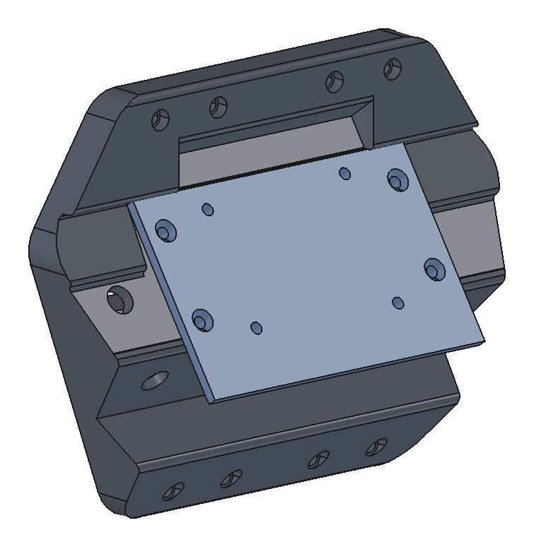
Rev D3.1 thickens the top flange from 8 to 12 mm, closing a 7 mm slot that ran across the whole D3 plate, and leaves solid plate around the bottom inserts and across the top band. The side walls now stop where the two sensor pads meet, so the nose and its sides are filler and TPU, which crush, rather than thin rigid cantilevers. Same model again, now 349,000 nodes; the side impact loads the two slanted faces of the hexagon and the corner cases load its corner arcs.
Rev D3 mount from behind. The open slot across the top is the thin band the study flagged.Rev D3.1 mount from behind. The slot is closed, the plate is solid above and below the pockets, and the outline is a hexagon.
Case
Peak, MPa
First yield (J) or safety factor, PA12
Rev B
D3
D3.1
Rev B
D3
D3.1
100 g forward
13.2
9.6
6.3
SF 3.6
SF 5.0
SF 7.6
100 g down
6.5
7.1
3.4
SF 7.4
SF 6.7
SF 14.0
100 g sideways
6.8
16.9
9.0
SF 7.1
SF 2.8
SF 5.4
Head-on via lidar
27.0
22.6
13.3
2.17 J
3.90 J
8.30 J
Face-plant
10.4
11.7
8.3
3.70 J
2.92 J
5.26 J
Top impact
21.5
14.9
7.9
1.13 J
1.76 J
5.82 J
Side impact
21.8
34.4
16.1
1.41 J
0.88 J
1.70 J
Top-front edge, 45°
12.3
10.5
8.7
–
–
–
Top-right corner
11.5
22.8
21.3
2.89 J
0.83 J
0.92 J
Top-left corner
13.0
23.0
22.0
2.23 J
0.81 J
0.87 J
Bottom-right corner
29.6
58.0
43.9
0.55 J
0.23 J
0.32 J
Bottom-left corner
35.7
59.4
41.8
0.41 J
0.22 J
0.36 J
Peak stress is per kN for impacts and at 100 g for the g-load cases. The right-hand columns are the energy to first yield for impacts, and the safety factor at 100 g for the g-loads.
Rev D3.1 beats Rev B in 8 of the 12 cases, most by a wide margin: 8.3 J to first yield head-on against 2.2 J, 5.8 J on top against 1.1 J, 5.3 J for a face-plant against 3.7 J, and a safety factor of 7.6 at 100 g forward against 3.6. Head-on stiffness is 3541 N/mm, against 2664 for Rev B and 1375 for D3.
The four corner cases are still weaker than Rev B: about 0.9 J on the top corners (Rev B 2.2–2.9 J) and 0.32–0.36 J on the bottom ones (Rev B 0.41–0.55 J). All four peak in the 2 mm web behind each heat-set insert, because the hexagon's corner arcs now sit right over the inserts. As in the earlier studies, the model holds the head only at the inserts; on the robot the back face also bears on the body brackets, so these corner numbers are an upper bound.
Rev D3.1 wasn’t print-ready either. The corners pointed to a thicker insert web, 2 mm to 3–4 mm at all eight inserts.
Rev D3.1 exploded: mount, the two sensors, upper and lower filler, TPU bumper.Side section. The lidar sits on top, tilted 35° up; the D435 sits below, pointing 42° down.
Rev D3.3: stronger on top and sides, a thin neck behind the lidar
Same model as before: the mount alone in PA12, held at the eight inserts, impacts at 1 kN and g-loads at 100 g. The mesh grew to 426,000 nodes, and CalculiX's direct solver ran out of memory on it, so this run used its iterative Cholesky solver.
Rev D3.3 mount with the separate 6 mm lidar plate. There are no hood walls; the filler and bumper form the head around it.Rev D3.3 exploded: mount, lidar plate, the two sensors, upper and lower filler, TPU bumper.
Case, mount only
D3.1, MPa
D3.3, MPa
100 g forward
6.3
15.4
100 g down
3.4
6.1
100 g sideways
9.0
6.8
Head-on via lidar
13.3
38.1
Face-plant
8.3
9.2
Top impact
7.9
3.7
Side impact
16.1
8.7
Top-front edge, 45°
8.7
14.8
Top-right corner
21.3
34.7
Top-left corner
22.0
35.1
Bottom-right corner
43.9
44.8
Bottom-left corner
41.8
44.9
Peak stress per kN for impacts and at 100 g for the g-loads; lower is better. Without hood walls, the full-width plate carries top, side and sideways loads directly, and all three improved: the top impact fell from 7.9 to 3.7 MPa per kN. Three cases got worse. The head-on hit through the lidar is 2.9 times higher, 100 g forward 2.4 times, and the top corners 1.6 times. The bottom corners are about the same.
All three regressions peak at one spot: a thin neck behind the lidar’s upper edge. The tilted lidar body comes within about 3 mm of the mount’s back face, so across the lidar’s width the mount is cut out in front to clear it and is only 3.5–8 mm thick, front to back. Just outside the lidar’s width it is 12 mm, with a sharp 5 mm step between the two.
These mount-only numbers are the pessimistic case, because nothing else in the head carries load. The fix designed for the next revision blends the step into a ramp of about 31° that reaches the full 12 mm a little further out. It hasn’t been analysed yet. Moving the lidar 3–4 mm forward would thicken the neck itself, but it would lengthen the head and change the sensor pose, so I didn’t.
With the filler bonded in
A second run fused the mount, the lidar plate and both fillers into one body, so the filler carries load. There the mount’s peak isn’t at the neck at all. With a PA12 filler, the head-on hit puts 18.8 MPa per kN into the mount, near the lower edge of the lidar plate, and it takes 1.18 J to first yield. The real filler is held only by the bumper, so it takes compression but not tension or shear: the truth lies between the two models. The weakest case is a bottom corner, at 0.56 J. A PETG filler at 45% infill yields much sooner itself: 0.22 J head-on and 0.09 J for a face-plant.
Rev D3.3 side section: the lidar on its plate on top, the D435 below, filler and TPU around both.
The neck is a margin weak spot, not a failure. The blended step goes into the next revision, which will be re-run on the head-on, 100 g forward and top-corner cases before anything is printed.
What's still open
Rev D3.3 has a thin neck behind the lidar that takes the head-on, 100 g forward and top-corner loads in the mount-only model. A blended step is designed for the next revision but not yet analysed.
The bottom corners have been the weakest case since Rev D3, and D3.3 doesn’t change them.
Rev C was never re-analysed, so its wider rib's gain is unverified.
The plug sizes in the script are assumptions, not measurements. They're 24 mm for the lidar's right-angle plug and its bend, and 12 × 13 × 7 mm for the USB-C plug.
Linear statics can't follow what happens after first yield. The bumper and brackets aren't modelled structurally, the filler only in the bonded best case, and the material values are datasheet figures, not measurements of my prints.
TPU brackets would add a large cushion. But the head could then shift under load, which matters for the camera's calibration against the body.
Lab reports
These are the reports written during the work, unedited, as they were at the time.
The full linear FEM report: findings, Rev A against Rev B, the filler comparison, materials, the g-load safety factors, stress maps and the number tables.
An interactive 3D viewer for the Rev A, B, D3, D3.1 and D3.3 results, with a side-by-side Rev B against Rev D3.3 mode. Pick a load case and a material, drag the load or play a trip or tip-over pulse, and watch where the mount first yields. Doesn't include the filler runs or Rev C.